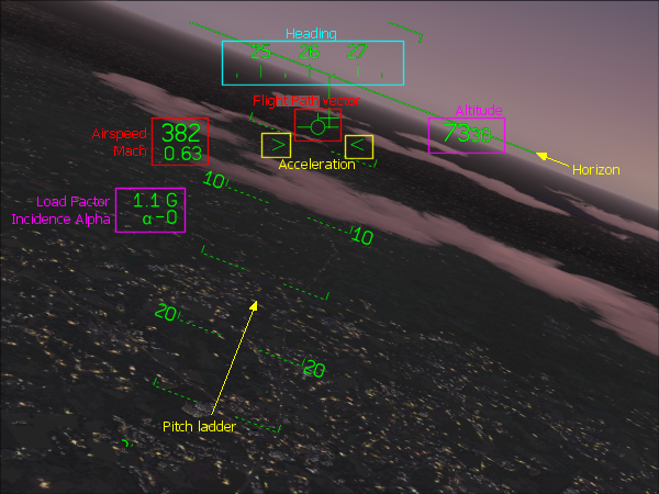
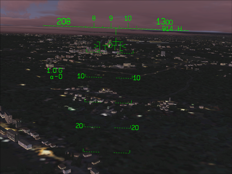
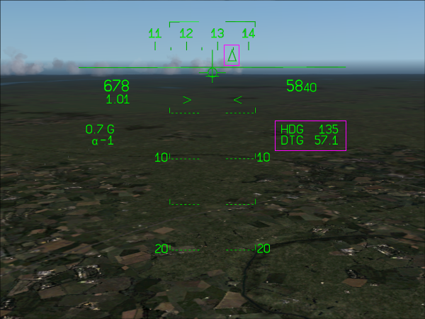
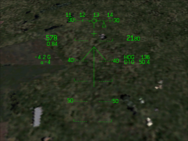
HUD layout in full screen mode
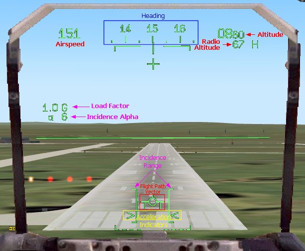
HUD layout in landing mode
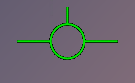 Speed vector shape when gear is up |  Speed vector shape when gear is down and locked |
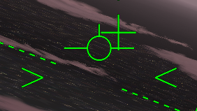 Deceleration | 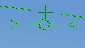 Constant speed | 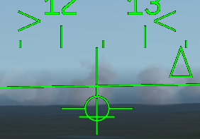 Acceleration |
Standard engine power | 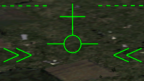 Afterburners on |
 Landing preparation is almost perfect: the speed vector is in the incidence range, speed is constant, the gear is down and locked. The speed is a little high. (click to enlarge) | 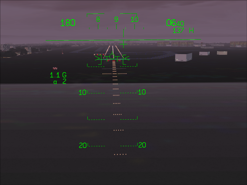 Close to land, the aircraft situation is perfect: airspeed is good, the speed vector is aligned with the runway and still in the incidence range, the speed is constant and the gear is OK. (click to enlarge) |
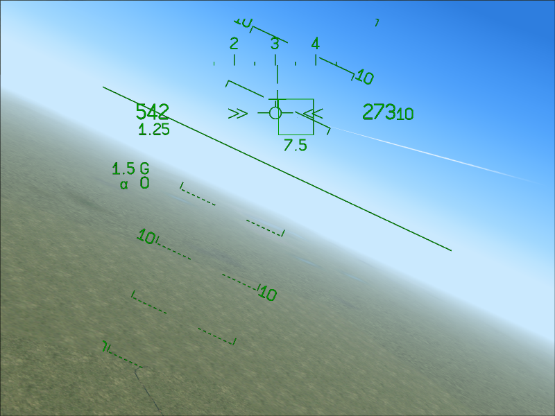
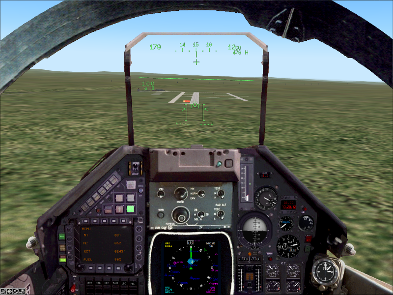 The situation is good but the speed vector is almost out of the incidence range. (click to enlarge) | 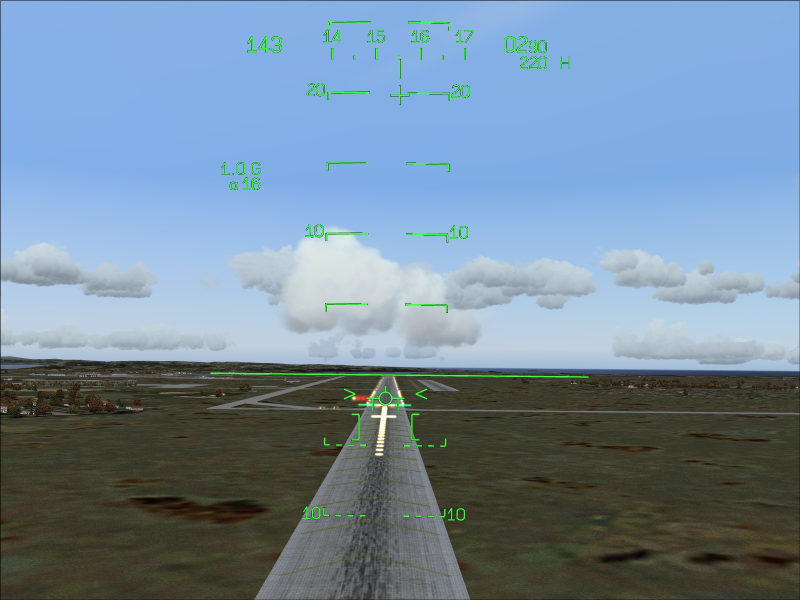 Bad situation: the speed vector is out of the incidence range. The incidence is too high and speed is low. (click to enlarge) | 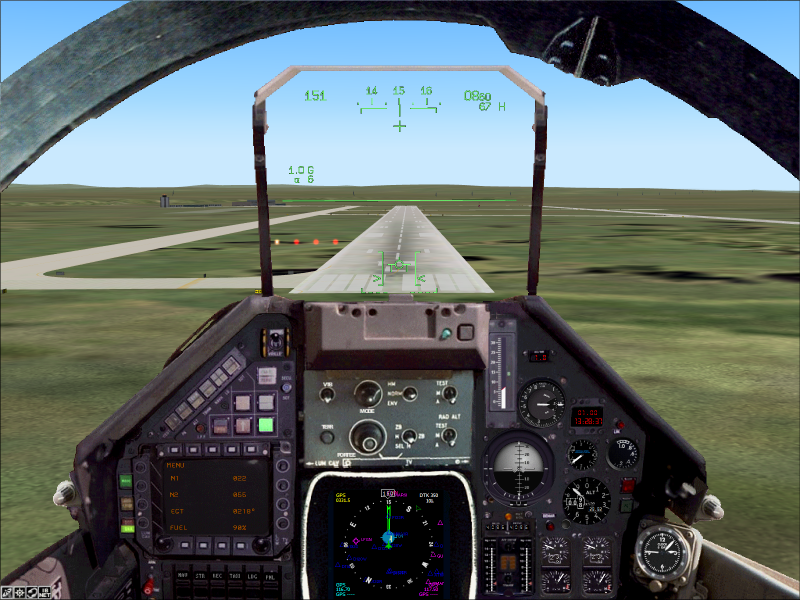 The speed is low and the aircraft is decelerating. (click to enlarge) |
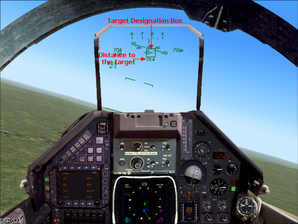
 At 7.5 NM, the target is hardly visible (the contrails are visible), the designation box shows the direction. (click to enlarge) | 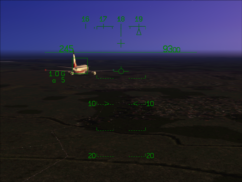 At less than 1 NM, the distance information disappears. The target is now visible. (click to enlarge) |
| gauge00=Mirage_4000!HUD Main,362,96,300,290 |
| [Window05] position=8 size_mm=1024,768 child_3d=1 background_color=0,0,0 ident=MINIPANEL gauge00=Mirage_4000!HUD Full, 190,35,644,660 |