Layout

The HUD information layout is shown on the images below, in 2D panel view and in full-screen view.


All the necessary flight information is displayed on the HUD so that you can fly the aircraft while looking outside:
Expert users might be interested in learning how to integrate this HUD in any panel. This section is dedicated to people who know how to edit a panel though the panel.cfg file. If you think you can do this, click here to access the HUD integration section.

Flight Path Vector

This is definitely the most important part of the HUD. Unlike classic aircraft instruments, such as the attitude indicator and the compass, the flight path vector, aka velocity vector, shows exactly where the aircraft is flying. You can fly the aircraft through its trajectory. When the flight path vector is above the synthetic horizon, the aircraft climbs. If it is below the horizon, the aircraft descends, even if the nose is above the horizon.
The flight path vector is accurate and refreshed in real-time.

Low-Level Flight

On these images of a low-level flight, the flight path vector is positioned just above the mountain top to make sure the aircraft will fly over the mountain and not crash into it. As long as the flight path vector is maintained above the mountain, the aircraft will fly over the mountain.


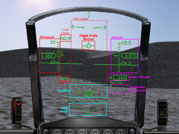
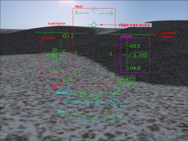
The flight path vector is maintained above the mountain, the aircraft will fly over the mountain
(click to enlarge)

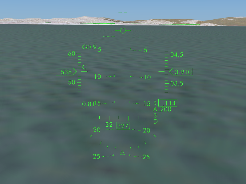
Low-level flight is easy, even at very low altitude. See the radio-altimeter: 114 feet.
(click to enlarge)

Outside view: the aircraft is flying at very low altitude. Easy...
(click to enlarge)

Landing with the HUD

When the landing gear is extended, the HUD automatically switches to the landing mode. The heading indicator is moved to the upper part of the display and a new symbol appears: the landing incidence guide. It shows the range of correct incidence for landing. You should maintain the flight path vector within this range to make a perfect landing.
When the aircraft is in landing configuration (gear extended, flaps and slats deployed, airspeed around 150-180 knots), the flight path vector just has to be aligned with the runway entry to guide the aircraft to landing.

The sequence shows an almost perfect landing using the HUD flight path vector and incidence indicator:

Click to enlarge
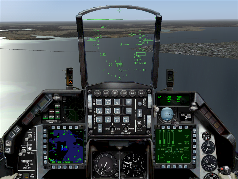
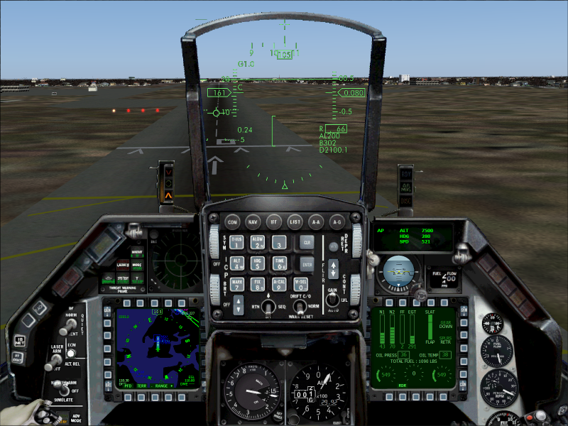
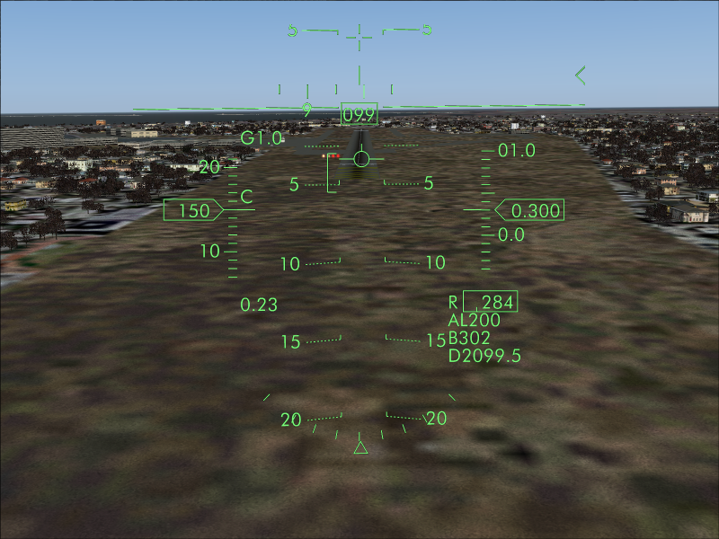
The flight path vector is positioned on the runway entry and it is in the correct 
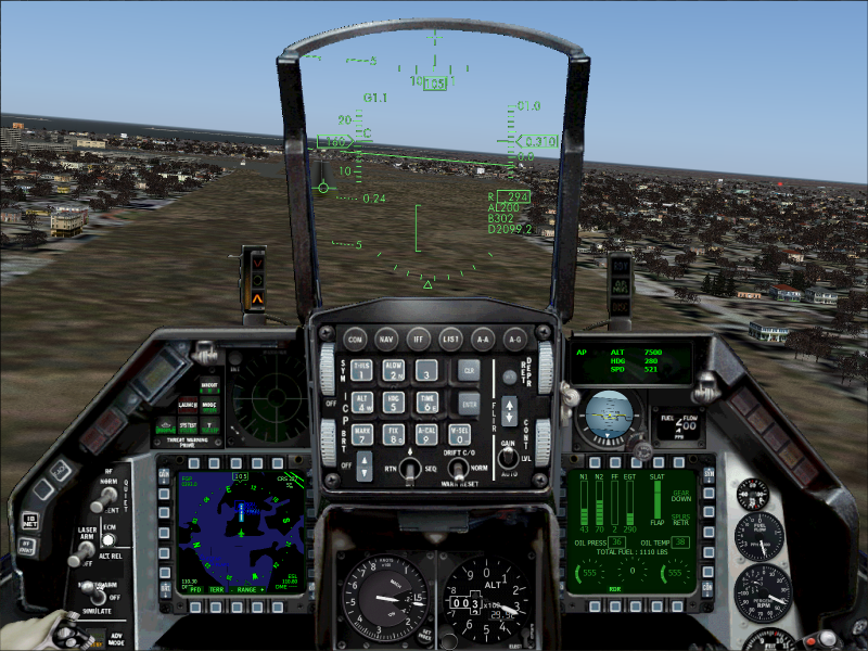
incidence range. The aircraft is on the glideslope, perfect.
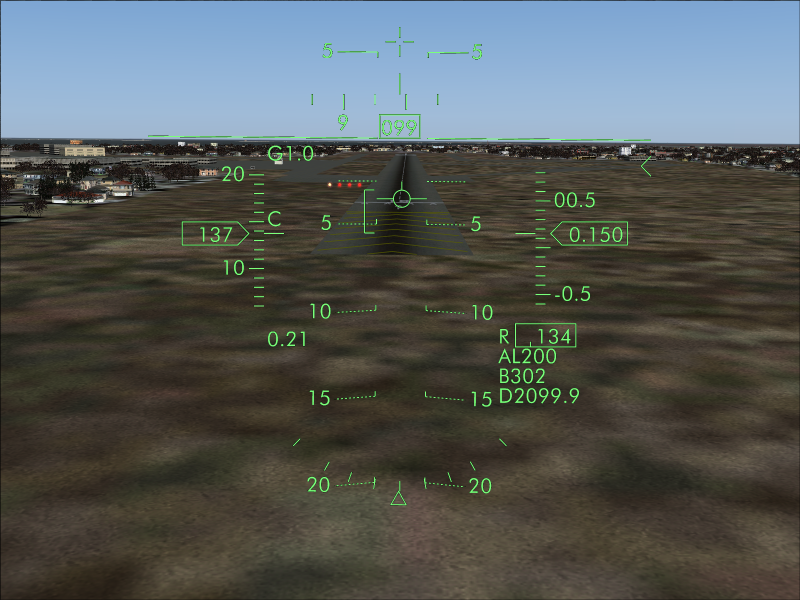
Click to enlarge
As the aircraft gets closer from the runway, it is a little low on the glidepath, but the flight path vector is still aligned with the runway and 
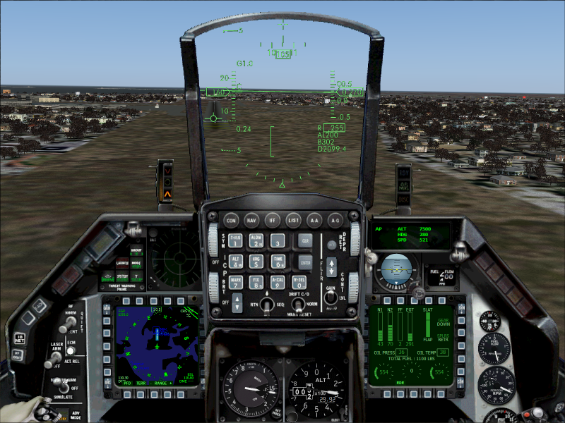
the incidence is good.
Click to enlarge
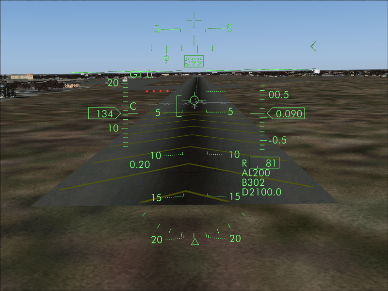
The flight path vector is maintained in the right incidence range, still aligned with the runway. The airspeed is a little low, but still good.
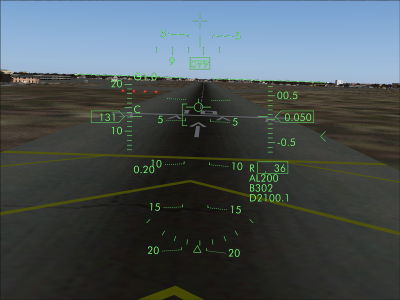
Click to enlarge
The 
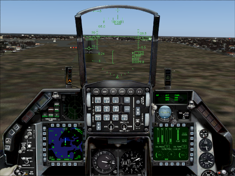
touchdown is very close. The flight path vector shows the aircraft will touch the ground at the very beginning of the runway. Easy with a good HUD...
(click any image to enlarge)

The HUD can show when the landing is not going right:


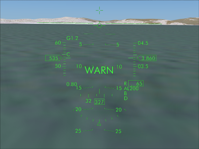
The flight path vector is positioned BEFORE the beginning of the runway.
The aircraft will not land safely...

The flight path vector is above the incidence range indicator
and the speed is too high.
(click any image to enlarge)

Managing Cross Wind

The HUD lets you see visually the wind drift caused by the cross wind. The flight path vector and pitch ladder move laterally to show exactly where the aircraft is flying, so if they move to the right, it means the aircraft is "pushed" on the right by the wind that comes from the left.


Click to enlarge
The wind coming from the left pushes the aircraft on the right.
The flight path vector and pitch ladder are shifted to the right.
(click to enlarge)

Using the HUD, cross wind landings become easy after a little training. Even if the wind is strong, you just have to keep the flight path vector aligned with the runway:

(click any image to enlarge)

This landing sequence shows the aircraft is flying in the direction of the runway even if the nose is not heading to the runway. This is easily managed with the HUD flight path vector. The landing is not perfect because the flight path vector is not in the correct incidence range. The approach descent is too flat and the speed is too high, but this is safe when the wind is blowing.

Navigation Information

If a flight plan has been entered or loaded in the GPS, the HUD provides navigation information to fly to the next waypoint.
The bearing and distance to the next waypoint are displayed.
A diamond shows the direction of the next waypoint, if it is in sight.
If no flight plan is defined, the bearing and distance are blank.

Target Designation Box

The radar developed by Eric Marciano must be installed to enable this feature.
The target designation box shows the direction of the target selected on the radar (even if the target is too far to be visible) and the distance to the target (in NM), below the box. It allows you to fly yor aircraft to the target for interception.
When the distance to the target is less that 1 NM, the distance stops being displayed.

The target is at 27.2 NM, beyond visual range. The speed vector is aligned with the
target designation box to fly directly to the target.


Click to enlarge
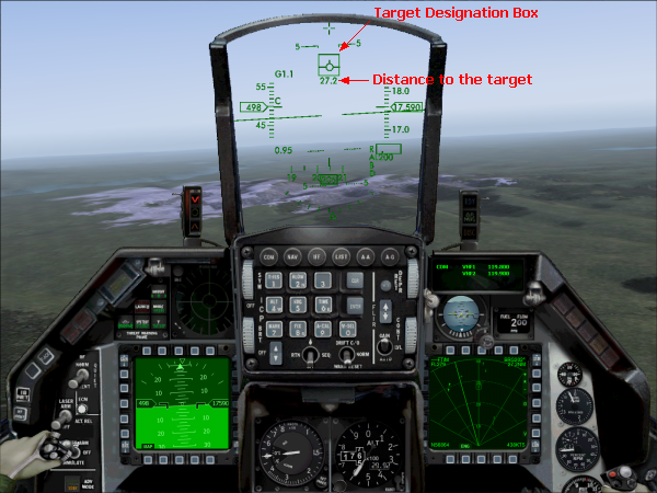
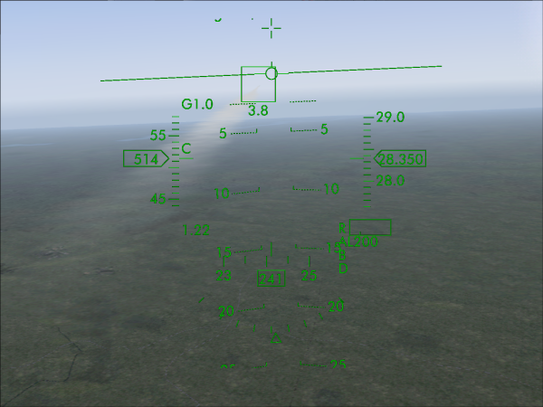
At 3.8 NM, the target is hardly visible (the contrails
are visible), the designation box shows the direction.
Click to enlarge
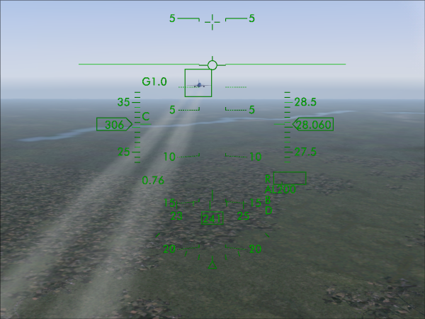
At less than 1 NM, the distance information
disappears. The target is now visible.

The target designation box is active as long as a target is selected on the radar. If you unselect the radar target, the box disappears.

Alert Messages

The HUD displays alert messages when needed, such as the warning message shown on the image below.
The possible messages are:
Click to enlarge
The altitude is low and the aircraft is descending.
It triggers a warning message.
(click to enlarge)

F-16 HUD Integration

The best way to understand the HUD panel integration is to see how it is integrated in the F-16 panel described here. The integration is exactly the same in FS2004 and FSX.
Basically, the HUD is an XML gauge that is listed in the panel.cfg just like any other gauge. In fact, the HUD provided here has 2 gauges: 1 for the 2D/3D panel integration and 1 for the full-screen usage using the "mini-panel" feature of FS2004/FSX.

In order to have the HUD showing in a panel, edit the panel.cfg and use the following gauges:
 Keep in mind that the F16_HUD.cab file must be in the panel directory if you want to have the HUD working.

Here is the example of the F-16 panel:

gauge00=F16_HUD!Main, 353,35,320,330

Just like for any other gauge, the HUD is positioned at 353,35 and its size is 320 by 330.

The HUD full-screen integration uses the mini-panel feature of FS2004/FSX. This is why it must be integrated in a separate panel window which identifier is MINIPANEL. Here is how it is done in the F-16 panel:

[Window09]
position=8
size_mm=1024,768
child_3d=1
background_color=0,0,0
ident=MINIPANEL

gauge00=F16_HUD!Full, 190,35,644,660

The [window09] section defines this window as a mini-panel, which includes the HUD in full-screen mode. Consequently, the HUD will appear in full-screen when you press the W key. Pressing the W key switches the panel off, which makes the mini-panel appear. Pressing W again switches the mini-panel off, and pressing W again brings the panel back.

For more information about the integration of gauges in a panel, please refer to the Microsoft Panel SDK.